
Constructing an Equatorial Wedge for the Celestron SLT/GT Goto Mount
A couple of years ago, when I was trying to take wide-field (nightscape) Astro-images with a
So I attempted to construct a barn door tracker. I started down this path because I wanted something inexpensive, small, lightweight and easy to set up. This project proved to be difficult to finish as I could not find a 1 RPM synchronous motor. I gave up on the Barn Door tracker project and started using my large telescope mount (CPC 1100 on the HD Pro equatorial wedge) onto which I affixed my
So fast forward two years. I started seeing used Celestron SLT/GT
My version of the Equatorial Wedge
This wedge was designed and constructed to be lightweight but could still carry at least a 5-pound payload. The SLT/GT mount can only handle 8 pounds so my goal was to keep everything on the mount at 4 pounds or less. As this project progressed, I realized that it would be the perfect entry-level setup for beginning
1. A suitable tripod
2. A Celestron hand controller (if one didn’t come with the mount purchase)
3. A vixen style bar for attaching the camera to the mount
4. A small telescope (50 – 80mm) for the
Construction materials:
Wood: (see figure 1)
• 6” x 6”, 1” thick pine board for the Tripod Disk,
• 6” x 21” piece of 5/16” plywood for the Base and Wedge Plates
• 2) 3” x 1 ½” 1” thick piece of pine for the Dowel Blocks
• 5 ¼” long piece of ¾” diameter pine dowel
• 2) 1” x 1” pine board squares to secure the cup hooks (not shown)
Hardware: (see figure 2)
• 2) #10-32 1” long thumb screws
• 3) 5/16-18 clamping knobs (2 closed end and one open end)
• 5/16 – 18 Insert nut
• 5) Auto Trim panel plugs
• 6” continuous hinge (I cut a 12” hinge in half)
• 12” long, 5/16 – 18 threaded bar (7” for Altitude adjustment rod and 5” to connect the tripod, disk, and base plate together allowing for the Azimuth adjustment)
• Acorn cap nut 5/16 - 18
• 7/16 x 2 ½ x .047 and 7/16 x 1 ½” x .047 -- 11-pound capacity spring pack.
• 2) cup hooks
• 2) 3/16 x 1” fender washers
• 6” disk of HDPE (I cut mine from a 1-gallon ice cream bucket lid, shown later)
• 2) 2 ½” wood screws (not shown), 6) ¼” beefy machine screws for the wedge plate hinge, 6) 1” wood screws (4 for the dowel blocks and 2 for cup hook blocks)
Tools used:
• Drill press (hand drill attached to a portable press)
• Jigsaw
• Various drill bits (normal and spade bits)
• Drill sanding disk
• Screwdrivers
• Various wood screws
• Wood glue
Construction Steps:
Cut, shape and drill the wood pieces according to the dimensions on the pictures below. The hole in the dowel blocks is ¾” wide using a spade drill bit at the blocks’ center point. The hole in the dowel’s center is 13/32" for the insert nut. Once this hole is drilled, screw in the insert nut into the dowel. This is the stationary pivot point through which the Altitude adjustment rod passes. Next, drill an 11/32" hole 1¼” from the hinge line on the centerline of the base plate. This is the hole that connects the tripod disk to the base plate and allows for the Azimuth adjustments. Now, using a ½” spade drill bit, drill a ½” wide channel 1 ½” long starting 3 ¼” from the end of the base plate. This channel is where the Altitude adjustment rod passes through the base plate.
The holes for the Tripod Disk are going to be unique to whatever tripod you choose to use. They need to be countersunk so the base plate sits flush on top of the tripod disk.
fig 3
Don’t forget to precisely measure and drill the 11/32" center hole for the 5” x 5/16” threaded Altitude adjustment rod (very important step). Lastly, drill the holes for the auto trim panel plugs based on the ones you acquired. They act as a low friction point for the Azimuth adjustments. So after this step, you should have a 6” round, 1” thick tripod disk, a 6” x 14” base plate, a 6” x 7” wedge plate, 2 - 3” x 1 ½” dowel blocks, and a 5 ¼” long piece of ¾” dowel. All as pictured above.
To drill the holes in the wedge plate, first, remove the metal mounting plate from the bottom of the SLT/GT mount (this plate is only used for measuring and NOT for connecting the SLT/GT mount to the wedge plate). Find the center of the wedge plate (horizontal and vertical) and orient the SLT/GT metal plate along the vertical axis, mark all 3 holes. The two outer holes are for the 10-32 thumbscrews and a ¼” center hole acts as the resting spot for the acorn cap nut. Countersink this hole to conform to the shape of the Acorn nut.
After you have drilled the above 3 holes, attach the mount, using the thumbscrews and fender washers. Snug the thumb screws tight enough that the small plastic feet on the base of the SLT/GT mount make 3 indentations on the wedge plate. Now drill 3 holes 3/16” deep using a ¼” drill bit. These holes allow the SLT/GT mount to sit flush against the wedge plate and act as a guide making it easier to attach the SLT mount to the wedge plate.
At this point, I spray painted all the wood pieces with ultra-flat black enamel paint. Each piece got 3 coats.
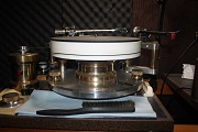
Here is a close-up of the Tripod Disk with all its holes and Auto trim panel plugs installed. 4 are shown, but a 5th one needs to be added in that big space. The HDPE disk will sit on top of the Tripod Disk.
Below is the HDPE (high-density polyurethane) disk I cut from an ice cream bucket lid. This disk sits between the tripod disk and the base plate and acts as a low friction point to allow for easier and more precise Azimuth adjustment when doing the Polar alignment.
- HDPE Disk.jpg (28.62 KiB) Viewed 42524 times
The Tripod Disk attached to the tripod. (see figure 7)
Assembling the pieces parts:
After the paint has thoroughly dried it’s time to assemble. There are two glue & screw operations. The first is to glue & screw the dowel blocks to the base plate as shown. Make sure to drill small pilot holes in the base plate and the blocks (2 screws per block). Don’t forget to insert the dowel between the two dowel block BEFORE you glue & screw. Also, make sure you get no glue on the dowel as it needs to move freely. Then glue & screw the 1” cup hook blocks to the top of the wedge plate flush with the top edge on the centerline of the wedge plate. Then glue & screw the second block 1” from the back edge of the base plate on the centerline of the base plate (1 wood screw per block).
When attaching the 6” hinge to the wedge plate and the base plate pay careful attention to the “squareness” of the hinge. I drew two guidelines for the hinge edge so I could tighten it down making sure it didn’t “wander”. Now cut your 12” 5/16-18 threaded bar into a 7” piece and a 5” piece. File the cut ends so that caps can be screwed onto them. Now thread the 7” bar (now called the Altitude adjustment rod) into and through the dowel’s insert nut. Once you have gotten about 2” through, screw on the Acorn cap nut and secure tightly. On the other end secure the closed-end clamping knob (I used a second nut to cinch up against the clamping knob to lock it in place).
Drill a small pilot hole for the cup hooks and screw them in place. Only attach the springs when the mount is in use. These springs put a lot of pressure on the cup hooks. It is also easier to attach the SLT/GT mount with the springs off.
EDIT: I have replaced the springs with a simple turnbuckle attached to the cup holder hooks just like you do with the springs. Using this hardware you are able to gently cinch down on the wedge plate to secure it in place.
Now insert the 5” Azimuth threaded bar (with a wide washer) up from the underside of the mount through the tripod disk, the HDPE disk, and then through the base plate. Put another wide washer over this threaded rod and then screw on the open-end clamping knob. Snug this assembly down. Now you are ready to attach the SLT/GT mount onto the wedge plate. Have the thumbscrews, fender washers, and springs ready to go. Line up the SLT/GT mount “feet” with holes in the wedge plate and then screw in the thumbscrews with fender washers in place. Once the thumbscrews are tight, attach the springs starting with the base plate then attach to the wedge plate.
At this point, you are done. All that is left is to attach your camera or your small telescope to the vixen bar and clamp that in place on the SLT/GT mount. Next, you will have to guess or measure the angle of the wedge plate so it matches your latitude. If you look closely you’ll see I’ve attached a clear plastic protractor marked with degrees to the base plate such that the center of the protractor is lined up with the apex of the hinge (see fig 8).
When finished it should look something like this.
The 70mm
Operating Instructions:
I believe it is easier to align the mount using a small telescope than trying to use the camera and its live view feature. Make sure all mount connections are snug.
First, orient the tripod so that the Altitude adjustment rod points to the North Star (Polaris). Next, set the wedge plate to the proper angle to represent your latitude. As a general rule of thumb as you go higher in latitude the closer the SLT mount arm points to the zenith. Or the lower you go in latitude the closer the SLT mount arm points to the horizon.
After turning on the power to the mount you will need to give the
After these steps are complete you will need to re-align the mount. Once you get good at these procedures you can get this done in a matter of minutes. In fact, I usually do it twice to make sure I’m as close to the
After the mount is “
Here is an example of the first set of images from this setup. As stated, I used this setup with my
Results:
Here are some of the very first images I acquired using this setup at my dark site on July 6, 2016. These images were taken with just the Canon T1i, my 18-55mm kit lens or the 50-250mm kit telephoto lens, and using just an intervalometer for acquiring multiple images.
This is a single unprocessed image of the Sagittarius region of the Milky Way. Lens at 25mm, 64 seconds, ISO 6400.
This is the same image cropped with minimal levels and curves stretching in PhotoShop.
This image of the same region used the lens at 25mm and is a stacked 15 x 4 minutes at ISO 1600 for a total of 1 hour of exposure time. It was stacked in Deep Sky Stacker 3.3.4 (
This image of M31 was taken with great haste as I was running out of night time. It uses my 50-250mm telephoto lens at 200mm. It is a
Here are some follow-up shots accomplished a few weeks later to further test out this setup.
M27 the Dumbbell. 10 30 second exposures for 5 minutes total, ISO 800 (from my red/orange backyard). 50-250mm lens at 130mm
M3 Glob. 10 3 minute exposures for 30 minutes total, ISO 800. 50-250mm lens at 100mm
M104 the Sombrero Galaxy. 10 3 minute exposures for 30 minutes total. 50-250mm lens at 100mm
In Conclusion:
Well, there you have it. An inexpensive wedge for an inexpensive
Cheers,
JT