Come join the friendliest, most engaging and inclusive astronomy forum geared for beginners and advanced telescope users, astrophotography devotees, plus check out our "Astro" goods vendors.
Come join the friendliest, most engaging and inclusive astronomy forum geared for beginners and advanced telescope users, astrophotography devotees, plus check out our "Astro" goods vendors.
I thought I had posted my one-piece worm assembly, but I can't find it here. It looks like this,
The motors are attached to the worm. The assembly tilts around the axis on the motor side. The other side is clamped down with a spring, in my case a piece of bicycle tube rubber. So, it is a motor-integrated one-piece worm assembly with SLW (spring-loaded worm). The pivot axis is tightened at the bottom with 2 small Belleville washers for some springiness. It was quite easy to assemble; one aluminum edge and 2 small aluminum plates with some holes drilled, glued together with metal epoxy.
I have been imaging with it for quite a while and it seems to work OK but not great. The best I can do is usually 0.7" RMS total but that is rare. About a week ago, when the seeing was good I got 0.5" RMS total - just where I want to be, and it was stable! Being inside an observatory makes it so much nicer to test than on the driveway out in the open.
So, I set out to do some testing. First off, I noticed that my calibration curves looked horrible mostly because the step size was too small. I adjusted that in Ekos and the back-and-forth curves had different angles. Looking at the assembly, I found that I had been way too careful with tightening the pivot axis down. Tightening it to the point where the friction started to set in, I finally got nice calibration curves.
I need to add that I had been working with a slightly off-balance RA axis, because I needed one more counterweight. The 11 + 21 lbs. were all the way at the end. I just ordered a 7 lbs. one from Losmandy to fix it. Meanwhile I kludged an extra AVX counterweight on the bar for testing.
Another thing I noticed is that my ASI120MM shows a jumpy behavior when sampling at 2 seconds. Short jump, large jump and repeat. At one second it does not show that behavior. When I started sampling at one second with 2x2 binning and it looked a lot better. I really need a better guide camera that supports USB3 not just USB2. Last week I ordered a QHY 5-III 200M that will arrive today.
Altogether I think I am close to reaching my 0.5" total RMS. Much more cannot be expected because of the direct worm drive with a 0.9 degree stepper at 32 microsteps. One worm rotation of 360/0.9 = 400 steps is 1 degree for the G11S, so that is 3600/(400*32) = 0.28" resolution. That calculation should hold for DEC; for RA you need to account for the mechanical dynamics because it is constantly pushing a load. That is rather unknown, but this should be a guideline. Anyway, the seeing usually limits the resolution to 0.5" to 1" per motor, I think, so 32 microsteps for 0.28" should be good enough.
... Henk. Telescopes: GSO 12" Astrograph, "Comet Hunter" MN152, ES ED127CF, ES ED80, WO Redcat51, Z12, AT6RC, Celestron Skymaster 20x80, Mounts and tripod: Losmandy G11S with OnStep, AVX, Tiltall, Cameras: ASI2600MC, ASI2600MM, ASI120 mini, Fuji X-a1, Canon XSi, T6, ELPH 100HS, DIY: OnStep controller, Pi4b/power rig, Afocal adapter, Foldable Dob base, Az/Alt Dob setting circles, Accessories: ZWO 36 mm filter wheel, TV Paracorr 2, Baader MPCC Mk III, ES FF, SSAG, QHY OAG-M, EAF electronic focuser, Plossls, Barlows, Telrad, Laser collimators (Seben LK1, Z12, Howie Glatter), Cheshire, 2 Orion RACIs 8x50, Software: KStars-Ekos, DSS, PHD2, Nebulosity, Photo Gallery, Gimp, CHDK, Computers:Pi4b, 2x running KStars/Ekos, Toshiba Satellite 17", Website:Henk's astro images
Like I reported on "what have you been up to", the QHY5-III 200M installation went off the rails. The camera works fine on Windows with SharpCap. Not with Ekos though. It shows up with a few red lights on the low-level control GUI. Some things look OK like the number of rows and columns but the camera doesn't work. Running lsusb I saw a different PID 193c than the 0200 that it should be according to rules.d.
I went to the QHYCCD pages and looked up the Linux installation instructions to install the latest. Now I get the proper 0200 PID but I can't even start the test configuration in Ekos anymore. The reason why, is that the top level indi driver indi_qhy_ccd was looking for libqhyccd.so.22 that I don't have anymore, just an updated version 23. I renamed it to 22 and put it in an LD_LIBRARY_PATH directory but of course, that cannot be expected to work.
I ran the AstroPi3 script to update my installation, and it does not fix it. Grrr. It looks like AstroPi3 just updates the core not the 3rd party drivers. That part still looks the way I left it (in shambles) so that's why. Now I need to figure out how to reinstall the 3rd party drivers. Maybe it's best to learn how to build the entire product (core and 3rd party) from scratch. Before I do that, I will try some simpler documented ways of updating them.
... Henk. Telescopes: GSO 12" Astrograph, "Comet Hunter" MN152, ES ED127CF, ES ED80, WO Redcat51, Z12, AT6RC, Celestron Skymaster 20x80, Mounts and tripod: Losmandy G11S with OnStep, AVX, Tiltall, Cameras: ASI2600MC, ASI2600MM, ASI120 mini, Fuji X-a1, Canon XSi, T6, ELPH 100HS, DIY: OnStep controller, Pi4b/power rig, Afocal adapter, Foldable Dob base, Az/Alt Dob setting circles, Accessories: ZWO 36 mm filter wheel, TV Paracorr 2, Baader MPCC Mk III, ES FF, SSAG, QHY OAG-M, EAF electronic focuser, Plossls, Barlows, Telrad, Laser collimators (Seben LK1, Z12, Howie Glatter), Cheshire, 2 Orion RACIs 8x50, Software: KStars-Ekos, DSS, PHD2, Nebulosity, Photo Gallery, Gimp, CHDK, Computers:Pi4b, 2x running KStars/Ekos, Toshiba Satellite 17", Website:Henk's astro images
Finally, I think I found the problem, and just sent a support ticket to QHYCCD. Their camera is called QHY 5-III 200M (Ver. 2). To me, this suggests that there has been a version 1. The 85-qhyccd.rules file has a PID of 0200 for a camera named QHYIII200. When connecting my camera, both in Windows and Linux, it reports a PID of 0201. That suggests to me that this camera requires a separate driver and a rules file update. I was able to get the camera to test OK in Linux using a test utility that scans for any QHYCCD camera. But Ekos cannot find it because it uses the rules file that has a PID of 0200 instead of 0201. Just changing the number doesn't work of course.
To get here, I spent 5 days testing, and building KStars and Ekos from scratch. That is something that developers do a lot, and once you know how to, it is easy. Just to get to that point is a whole different matter. It is very useful though; now I can build a new version any time I need to. Maybe I can even fix minor problems. In order to get it working I had to wipe my Pi4b to switch from 32-bit Raspbian Buster to 64-bit Raspbian Bullseye. I guess the latest OS versions are supported, older ones perhaps not, so flashing a new OS may be needed.
QHYCCD is supposed to get back to me within 24 hours. I am curious what they have to say, but I think I hit the nail on the head and that it will be easy for them to provide me with an SDK update soon.
... Henk. Telescopes: GSO 12" Astrograph, "Comet Hunter" MN152, ES ED127CF, ES ED80, WO Redcat51, Z12, AT6RC, Celestron Skymaster 20x80, Mounts and tripod: Losmandy G11S with OnStep, AVX, Tiltall, Cameras: ASI2600MC, ASI2600MM, ASI120 mini, Fuji X-a1, Canon XSi, T6, ELPH 100HS, DIY: OnStep controller, Pi4b/power rig, Afocal adapter, Foldable Dob base, Az/Alt Dob setting circles, Accessories: ZWO 36 mm filter wheel, TV Paracorr 2, Baader MPCC Mk III, ES FF, SSAG, QHY OAG-M, EAF electronic focuser, Plossls, Barlows, Telrad, Laser collimators (Seben LK1, Z12, Howie Glatter), Cheshire, 2 Orion RACIs 8x50, Software: KStars-Ekos, DSS, PHD2, Nebulosity, Photo Gallery, Gimp, CHDK, Computers:Pi4b, 2x running KStars/Ekos, Toshiba Satellite 17", Website:Henk's astro images
Good luck with the sdk and getting everything smoothed out.
Sounds like a lot, but also sounds like you are having fun!
Jim
Scopes: Explore Scientific ED102 APO, Sharpstar 61 EDPH II APO, Samyang 135 F2 (still on the Nikon).
Mount: Skywatcher HEQ5 Pro with Rowan Belt Mod
Stuff: ASI EAF Focus Motor (x2), ZWO OAG, ZWO 30 mm Guide Scope, ASI 220mm min, ASI 120mm mini, Stellarview 0.8 FR/FF, Sharpstar 0.8 FR/FF, Mele Overloock 3C.
Camera/Filters/Software: ASI 533 mc pro, ASI 120mm mini, ASI 220mm mini , IDAS LPS D-1, Optolong L-Enhance, ZWO UV/IR Cut, N.I.N.A., Green Swamp Server, PHD2, Adobe Photoshop CC, Pixinsight.
Dog and best bud: Jack
Sky: Bortle 6-7
My Astrobin: https://www.astrobin.com/users/Juno16/
And here I thought my switching out computers in the observatory this past week was a pain (PITA). To me, yours is an insurmountable task. I am impressed with what you're able to do Henk, it is laudable.
I hope everything turns out well.
∞ Primary Scopes: #1: Celestron CPC1100 #2: 8" f/7.5 Dob #3: CR150HD f/8 6" frac ∞ AP Scopes: #1: TPO 6" f/9 RC #2: ES 102 f/7 APO #3: ES 80mm f/6 APO ∞ G&G Scopes: #1: Meade 102mm f/7.8 #2: Bresser 102mm f/4.5 ∞ Guide Scopes: 70 & 80mm fracs -- The El Cheapo Bros. ∞ Mounts: iOptron CEM70AG, SW EQ6R, Celestron AVX, SLT & GT (Alt-Az), Meade DS2000 ∞ Cameras: #1: ZWO ASI294MC Pro #2: 662MC #3: 120MC, Canon T3i, Orion SSAG, WYZE Cam3 ∞ Binos: 10X50,11X70,15X70, 25X100 ∞ AP Gear: ZWO EAF and mini EFW and the Optolong L-eXteme filter ∞ EPs: ES 2": 21mm 100° & 30mm 82° Pentax XW: 7, 10, 14, & 20mm 70°
Searching the skies since 1966. "I never met a scope I didn't want to keep."
I had a few hiccups with networking that forced me to read up on Raspbian and fix the configuration files. I had unintentionally thoroughly messed them up using the GUI and was not able to connect at all. I had to hook up a monitor, keyboard and mouse to fix everything.
Tonight, I put everything back on the scope and got it working again. With the repeater I now have 3 access points. When I had given the main router (the weakest one) the highest priority, I lost the connection all the time. Setting it to the lowest priority fixed that. The Pi then connected to the 5G one that I had given the highest priority. After that the wireless worked fine.
I found that my power supply is just barely enough. If I run the Pi's fan off a 5V pin instead of a 3.3V pin, the system complains about lack of power and is failing all the time! I knew it was hanging by a thread and I need to take another look to see how I can fix it.
Then I had a lot of trouble finding stars in the camera. There was just one star visible, supposedly Vega. Thick fog, end of exercise.
... Henk. Telescopes: GSO 12" Astrograph, "Comet Hunter" MN152, ES ED127CF, ES ED80, WO Redcat51, Z12, AT6RC, Celestron Skymaster 20x80, Mounts and tripod: Losmandy G11S with OnStep, AVX, Tiltall, Cameras: ASI2600MC, ASI2600MM, ASI120 mini, Fuji X-a1, Canon XSi, T6, ELPH 100HS, DIY: OnStep controller, Pi4b/power rig, Afocal adapter, Foldable Dob base, Az/Alt Dob setting circles, Accessories: ZWO 36 mm filter wheel, TV Paracorr 2, Baader MPCC Mk III, ES FF, SSAG, QHY OAG-M, EAF electronic focuser, Plossls, Barlows, Telrad, Laser collimators (Seben LK1, Z12, Howie Glatter), Cheshire, 2 Orion RACIs 8x50, Software: KStars-Ekos, DSS, PHD2, Nebulosity, Photo Gallery, Gimp, CHDK, Computers:Pi4b, 2x running KStars/Ekos, Toshiba Satellite 17", Website:Henk's astro images
Graeme1858 wrote: ↑Tue Aug 08, 2023 9:42 am
Yeah, I'm impressed too!
I had to go on the NINA Discord to get the power arrangements right on my USBs so that the new camera could download.
Can you run the Pi fan from a separate supply through a relay controlled by the Pi?
Graeme
I had to combine a powered USB2 hub with a cut-up USB-A cable on a 12 to 5V DCDC buck converter to a USB-A to USB-C adapter for the main power. Its wires are pretty thin. Without the USB2 hub there is not enough power. I once tried hooking the 5V DC directly to the Pi4b pins but that is risky; power spikes can fry the Pi.
My power supply provides plenty (5A@12V=60W). Up to 36W goes to the 12-V ASI2600 cooler. The ASI2600 camera itself uses 4.7W (USB3). The ASI120MM uses 0.75W (USB3). The other devices (filter wheel, focuser) do not require USB3 so they are on the powered USB2 hub and do not burden the Pi. The Pi USB total output (2xUSB2 and 2xUSB3) is limited to 1.1A (5.5W). Clearly, I am walking a tight rope. The USB3 cameras use 5.45W total (Pi4b limit=5.5W). The fan uses 80mA (0.4W at 5V, 0.264W at 3.3V). The OnStep controller is connected to a USB2 port on the hub but also has its own power cable.
I think the solution is to replace my powered USB2 hub with a powered USB3 hub so I can run both cameras over the powered hub instead of directly off the Pi. I have one that can provide 20W. Let me work on that for the next rig that I was going to build.
... Henk. Telescopes: GSO 12" Astrograph, "Comet Hunter" MN152, ES ED127CF, ES ED80, WO Redcat51, Z12, AT6RC, Celestron Skymaster 20x80, Mounts and tripod: Losmandy G11S with OnStep, AVX, Tiltall, Cameras: ASI2600MC, ASI2600MM, ASI120 mini, Fuji X-a1, Canon XSi, T6, ELPH 100HS, DIY: OnStep controller, Pi4b/power rig, Afocal adapter, Foldable Dob base, Az/Alt Dob setting circles, Accessories: ZWO 36 mm filter wheel, TV Paracorr 2, Baader MPCC Mk III, ES FF, SSAG, QHY OAG-M, EAF electronic focuser, Plossls, Barlows, Telrad, Laser collimators (Seben LK1, Z12, Howie Glatter), Cheshire, 2 Orion RACIs 8x50, Software: KStars-Ekos, DSS, PHD2, Nebulosity, Photo Gallery, Gimp, CHDK, Computers:Pi4b, 2x running KStars/Ekos, Toshiba Satellite 17", Website:Henk's astro images
SkyHiker wrote: ↑Tue Aug 08, 2023 10:36 pm
I think the solution is to replace my powered USB2 hub with a powered USB3 hub so I can run both cameras over the powered hub instead of directly off the Pi. I have one that can provide 20W. Let me work on that for the next rig that I was going to build.
SkyHiker wrote: ↑Tue Aug 08, 2023 10:36 pm
I think the solution is to replace my powered USB2 hub with a powered USB3 hub so I can run both cameras over the powered hub instead of directly off the Pi. I have one that can provide 20W. Let me work on that for the next rig that I was going to build.
You mean, why spend $20 on a powered USB3 hub if you can buy a Pegasus for $340? Let me check, I don't need 4 12V outputs, only 1. I don't use dew heaters (yet); I would simply pack it up, it doesn't get humid too often here. The 4 USB ports are just enough for the focuser, filter wheel, imager and guide camera. Then again, I would have 2xUSB2 and 1xUSB3 left on the Pi if I need more. It has a B male for the PC connection, a cable like that on my ASI2600 camera. I suppose it's extra fast. And the form factor is nicer and smaller than my plywood rig with a 12 to 5 V DCDC and 7-port USB hub on it that will probably flash its lights and people will complain about that. Ok let me think about it. It would look less genuine than my plywood board that I named Medusa, of course.
BTW great news: For unclear reasons, the QHY 5-III 200M (Ver. 2) decided to start working. I have no clue why. I did a rebuild from source code yesterday and tried my Ekos configuration; it failed then. This morning I tried it again and it worked. I'm not cheering fully yet but it starts looking better.
... Henk. Telescopes: GSO 12" Astrograph, "Comet Hunter" MN152, ES ED127CF, ES ED80, WO Redcat51, Z12, AT6RC, Celestron Skymaster 20x80, Mounts and tripod: Losmandy G11S with OnStep, AVX, Tiltall, Cameras: ASI2600MC, ASI2600MM, ASI120 mini, Fuji X-a1, Canon XSi, T6, ELPH 100HS, DIY: OnStep controller, Pi4b/power rig, Afocal adapter, Foldable Dob base, Az/Alt Dob setting circles, Accessories: ZWO 36 mm filter wheel, TV Paracorr 2, Baader MPCC Mk III, ES FF, SSAG, QHY OAG-M, EAF electronic focuser, Plossls, Barlows, Telrad, Laser collimators (Seben LK1, Z12, Howie Glatter), Cheshire, 2 Orion RACIs 8x50, Software: KStars-Ekos, DSS, PHD2, Nebulosity, Photo Gallery, Gimp, CHDK, Computers:Pi4b, 2x running KStars/Ekos, Toshiba Satellite 17", Website:Henk's astro images
SkyHiker wrote: ↑Wed Aug 09, 2023 2:31 pm
BTW great news: For unclear reasons, the QHY 5-III 200M (Ver. 2) decided to start working. I have no clue why.
Maybe it was your unbridled wit that got it going?
SkyHiker wrote: ↑Wed Aug 09, 2023 2:31 pm
BTW great news: For unclear reasons, the QHY 5-III 200M (Ver. 2) decided to start working. I have no clue why.
Maybe it was your unbridled wit that got it going?
It must be. The first time I built Ekos from source it only got halfway done and hung; I restarted it. Yesterday it went through the whole way without problems, that's one remote possibility. It is possible that doing a dist_clean.sh made a difference, but does that matter? Everything gets reinstalled AFAIK. I tested the driver yesterday afterwards in Ekos and it showed a crash; today I did the same and it worked fine. The only difference is that I edited the configuration by pulling down the same choice (QHY CCD) that I had done before. It's black magic for now.
... Henk. Telescopes: GSO 12" Astrograph, "Comet Hunter" MN152, ES ED127CF, ES ED80, WO Redcat51, Z12, AT6RC, Celestron Skymaster 20x80, Mounts and tripod: Losmandy G11S with OnStep, AVX, Tiltall, Cameras: ASI2600MC, ASI2600MM, ASI120 mini, Fuji X-a1, Canon XSi, T6, ELPH 100HS, DIY: OnStep controller, Pi4b/power rig, Afocal adapter, Foldable Dob base, Az/Alt Dob setting circles, Accessories: ZWO 36 mm filter wheel, TV Paracorr 2, Baader MPCC Mk III, ES FF, SSAG, QHY OAG-M, EAF electronic focuser, Plossls, Barlows, Telrad, Laser collimators (Seben LK1, Z12, Howie Glatter), Cheshire, 2 Orion RACIs 8x50, Software: KStars-Ekos, DSS, PHD2, Nebulosity, Photo Gallery, Gimp, CHDK, Computers:Pi4b, 2x running KStars/Ekos, Toshiba Satellite 17", Website:Henk's astro images
SkyHiker wrote: ↑Tue Aug 08, 2023 10:36 pm
I think the solution is to replace my powered USB2 hub with a powered USB3 hub so I can run both cameras over the powered hub instead of directly off the Pi. I have one that can provide 20W. Let me work on that for the next rig that I was going to build.
Dang, you just made me $340 poorer before my 4th cup of coffee. It's one of those products I had decided I would never buy but this one looked too good!
... Henk. Telescopes: GSO 12" Astrograph, "Comet Hunter" MN152, ES ED127CF, ES ED80, WO Redcat51, Z12, AT6RC, Celestron Skymaster 20x80, Mounts and tripod: Losmandy G11S with OnStep, AVX, Tiltall, Cameras: ASI2600MC, ASI2600MM, ASI120 mini, Fuji X-a1, Canon XSi, T6, ELPH 100HS, DIY: OnStep controller, Pi4b/power rig, Afocal adapter, Foldable Dob base, Az/Alt Dob setting circles, Accessories: ZWO 36 mm filter wheel, TV Paracorr 2, Baader MPCC Mk III, ES FF, SSAG, QHY OAG-M, EAF electronic focuser, Plossls, Barlows, Telrad, Laser collimators (Seben LK1, Z12, Howie Glatter), Cheshire, 2 Orion RACIs 8x50, Software: KStars-Ekos, DSS, PHD2, Nebulosity, Photo Gallery, Gimp, CHDK, Computers:Pi4b, 2x running KStars/Ekos, Toshiba Satellite 17", Website:Henk's astro images
Just got an email from Agena Astro, they shipped the Pegasus box. I bet I'll get it tomorrow. They are amazing.
I just hooked up the QHY5III200M with the rest, and it works. However, dmesg keeps reporting a lack of voltage every time I take a sub with the main or guide cam. That's because I have to hungry guests on the Pi's USB3s. I can try a powered USB3 hub on it but if my Pegasus arrives tomorrow, why bother.
Last night I tested autoguiding and was able to get 0.6" RMS total regularly by paying attention to the balancing. At first, I got poor performance in DEC, and that was purely because it was off-balance when I checked. Fixing the balance fixed the results. The best balance check is by pulling the worm assemblies out and making sure that they snap back into place when you let go. I am happy that there's a good correlation.
One more thing that was brought to my attention last night in a Zoom club DIYer meeting, is that angular momentum is quadratic in the distance. In other words, moving 2 10-lbs. weights takes half the effort of moving 1 20-lbs. weight when just looking at inertia. The OTA on the other side cannot be reconfigured that way so the 1x20 effort is 1.5 times larger than the 2x10 effort. The tracking and autoguiding effort spent on inertia can thus be reduced by 1/3. My weights are largely at the end of the counterweight bar, so it might be useful to add another weight of at least 11 lbs. That may also increase the friction of course and lighten my wallet, but I'll keep it in mind.
... Henk. Telescopes: GSO 12" Astrograph, "Comet Hunter" MN152, ES ED127CF, ES ED80, WO Redcat51, Z12, AT6RC, Celestron Skymaster 20x80, Mounts and tripod: Losmandy G11S with OnStep, AVX, Tiltall, Cameras: ASI2600MC, ASI2600MM, ASI120 mini, Fuji X-a1, Canon XSi, T6, ELPH 100HS, DIY: OnStep controller, Pi4b/power rig, Afocal adapter, Foldable Dob base, Az/Alt Dob setting circles, Accessories: ZWO 36 mm filter wheel, TV Paracorr 2, Baader MPCC Mk III, ES FF, SSAG, QHY OAG-M, EAF electronic focuser, Plossls, Barlows, Telrad, Laser collimators (Seben LK1, Z12, Howie Glatter), Cheshire, 2 Orion RACIs 8x50, Software: KStars-Ekos, DSS, PHD2, Nebulosity, Photo Gallery, Gimp, CHDK, Computers:Pi4b, 2x running KStars/Ekos, Toshiba Satellite 17", Website:Henk's astro images
SkyHiker wrote: ↑Tue Aug 08, 2023 10:36 pm
I think the solution is to replace my powered USB2 hub with a powered USB3 hub so I can run both cameras over the powered hub instead of directly off the Pi. I have one that can provide 20W. Let me work on that for the next rig that I was going to build.
@Graeme1858, that Pegasus box works beautifully, thanks for recommending it. It is about the same size as my Pi4b, when stuck together as one unit it is really compact. The "not enough power" alarms from dmesg on the Pi are gone, as expected. Now I just need to look for some shorter cables or fold them up better.
... Henk. Telescopes: GSO 12" Astrograph, "Comet Hunter" MN152, ES ED127CF, ES ED80, WO Redcat51, Z12, AT6RC, Celestron Skymaster 20x80, Mounts and tripod: Losmandy G11S with OnStep, AVX, Tiltall, Cameras: ASI2600MC, ASI2600MM, ASI120 mini, Fuji X-a1, Canon XSi, T6, ELPH 100HS, DIY: OnStep controller, Pi4b/power rig, Afocal adapter, Foldable Dob base, Az/Alt Dob setting circles, Accessories: ZWO 36 mm filter wheel, TV Paracorr 2, Baader MPCC Mk III, ES FF, SSAG, QHY OAG-M, EAF electronic focuser, Plossls, Barlows, Telrad, Laser collimators (Seben LK1, Z12, Howie Glatter), Cheshire, 2 Orion RACIs 8x50, Software: KStars-Ekos, DSS, PHD2, Nebulosity, Photo Gallery, Gimp, CHDK, Computers:Pi4b, 2x running KStars/Ekos, Toshiba Satellite 17", Website:Henk's astro images
Good polar alignment helps too, of course. Someone at my Tuesday night SBAU astro Zoom workshop hinted at this so I rechecked my PA and found that it must have been about 4.5 arc minutes off. And that was after I "fixed" it. The reason is that I had to learn how to polar align with the NCP behind a wall. Ekos has the capability of doing that using three plate-solved images at different angles. I just needed some more practice doing that, and last got it down to about 1.5 arc minutes. It helps to do a second PA round to check the result of the previous PA. It got me down to about 0.5" RMS total, the goal that I had set for myself. Summarizing the improvements,
Build spring-loaded worm assemblies with motor integrated to minimize axial misalignment
Tighten the Bellevilles on the pivot axis of the spring-loaded worms to minimize wobble
Tighten the springs of the spring-loaded worms enough to achieve zero backlash
Add a counterweight to fix the imbalance due to lack of sufficient counterweights
Add another one (TBD) to move the weights up the shaft and reduce the rotational moment of inertia
Place the coma corrector at the right backfocus for sharp guide stars
Get a better guide camera for more stars, less noise and larger cache to fix latency issues
Autoguide at 1 second sampling with 3x3 binning and multi-star SEP
Accurate polar alignment
An observatory to reduce the effect of wind (astrograph = big sail)
Add a Pegasus box to offload the power for the cameras from the Pi4b
Activate GPG (adaptive PEC)
That got me to these types of calibration curves and autoguiding below that I am happy with. The autoguiding is mostly around 0.5 to 0.6" RMS total but dips into 0.4 at some places. It's a matter of being a bit more diligent to achieve 0.5 consistently but I think I've got it.
... Henk. Telescopes: GSO 12" Astrograph, "Comet Hunter" MN152, ES ED127CF, ES ED80, WO Redcat51, Z12, AT6RC, Celestron Skymaster 20x80, Mounts and tripod: Losmandy G11S with OnStep, AVX, Tiltall, Cameras: ASI2600MC, ASI2600MM, ASI120 mini, Fuji X-a1, Canon XSi, T6, ELPH 100HS, DIY: OnStep controller, Pi4b/power rig, Afocal adapter, Foldable Dob base, Az/Alt Dob setting circles, Accessories: ZWO 36 mm filter wheel, TV Paracorr 2, Baader MPCC Mk III, ES FF, SSAG, QHY OAG-M, EAF electronic focuser, Plossls, Barlows, Telrad, Laser collimators (Seben LK1, Z12, Howie Glatter), Cheshire, 2 Orion RACIs 8x50, Software: KStars-Ekos, DSS, PHD2, Nebulosity, Photo Gallery, Gimp, CHDK, Computers:Pi4b, 2x running KStars/Ekos, Toshiba Satellite 17", Website:Henk's astro images
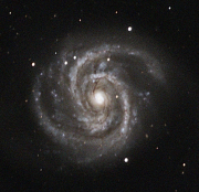
I still have some coma problems. See the parachute-like smears below for all 4 corners. This affects the quality of the guide stars because they are taken from the edge. I noticed that if the guide stars have smears they don't work nearly as well as round ones.
I managed to get 56 mm backfocus while I need 55 mm. I just ordered a whole set of M42 rings 3, 5, 7, 10, 12, 15, 20, 30mm where I can fine tune the distance.
I am OK with the over all image. This is 1 hour of minutes preprocessed in PI (WBPP, DBE) the rest in Gimp (curves, gradient, despeckle, erode, sharpen). BlurXTerminator did not work well at all on this one for some reason, I need to figure out why.
... Henk. Telescopes: GSO 12" Astrograph, "Comet Hunter" MN152, ES ED127CF, ES ED80, WO Redcat51, Z12, AT6RC, Celestron Skymaster 20x80, Mounts and tripod: Losmandy G11S with OnStep, AVX, Tiltall, Cameras: ASI2600MC, ASI2600MM, ASI120 mini, Fuji X-a1, Canon XSi, T6, ELPH 100HS, DIY: OnStep controller, Pi4b/power rig, Afocal adapter, Foldable Dob base, Az/Alt Dob setting circles, Accessories: ZWO 36 mm filter wheel, TV Paracorr 2, Baader MPCC Mk III, ES FF, SSAG, QHY OAG-M, EAF electronic focuser, Plossls, Barlows, Telrad, Laser collimators (Seben LK1, Z12, Howie Glatter), Cheshire, 2 Orion RACIs 8x50, Software: KStars-Ekos, DSS, PHD2, Nebulosity, Photo Gallery, Gimp, CHDK, Computers:Pi4b, 2x running KStars/Ekos, Toshiba Satellite 17", Website:Henk's astro images